Analysis of Intensity Modulation Response of Analog Fiber-Optic Links
V.V. Shcherbakov1, A.F. Solodkov1, A.A. Zadernovsky2
1JSC “Center VOSPI” Moscow, Russia info@centervospi.ru
2Department of physics Moscow Technological University, MIREA Moscow, Russia zadernovsky@mirea.ru
*This work was partially supported by Ministry of Education and Science of the Russian Federation.
I. INTRODUCTION
Fiber-optic links are widely used in various areas of science and technology. In the field of telecommunications, digital data transmission systems are mostly employed. However, the simplest analog systems with direct intensity modulation (IM) of the light produced by a semiconductor laser, transportation of the optical signal through an optical fiber and, finally, direct detection (DD) of the optical signal by a photodiode at the output of the fiber, are in demand for a variety of applications. The direct intensity modulation can be achieved by varying the drive current of the semiconductor laser. Unfortunately, this current variation not only modulates the laser light intensity, but induces a parasitic optical frequency modulation, the effect which is referred to as laser chirp. Frequency chirp of laser light can cause degradation and harmonic distortions of the transmitted signals after propagation in dispersive optical fiber. Nevertheless, the analog IM/DD fiber-optic links with direct intensity modulation are often the only option for some applications, and, at the same time, they offer a reliable and cost-effective solution.
In this paper we perform an analysis of signal transmission in analog IM/DD fiber-optic links with direct intensity modulation. It is worth noting that in the majority of studies of such systems, either numerical analysis or rather complicated mathematical apparatus are usually used. This makes difficult obtaining simple analytical expressions suitable for the engineering design. This work is intended to fill this gap. We derive a simple analytical expression for the frequencies of the signals with minimum or with maximum power at the output of a fiber. We also derive a simple analytical expression for the frequencies at which there will be no dispersive signal harmonic distortions. Experimental results supporting the theoretical calculations are presented.
II. THEORY
A. Electrical-to-optical conversion
Varying the drive current of a semiconductor laser is the easiest way to convert electrical signals into optical ones. At moderate radiation powers the laser watt-ampere characteristic is well described by a linear function. Therefore, a harmonic signal of electric current modulation with angular frequency ωm , the phase φm and the depth of modulation m is converted into a similar signal of the laser output optical power
| P = P0 (1 + m cos( ωm t + φm )). | (1) |
The associated electromagnetic wave with the carrier frequency ω0 and the phase φ0 is given by
| |
(2) |
With account of frequency chirp the phase φ0 in (2) is not a constant and should be determined from the equation [1]
 , , |
(3) |
where α is the Henry factor, and k is a laser-specific parameter known as the adiabatic chirp coefficient. Integration in (3) yields the following expression for the phase
| |
(4) |
where φ0 is the integration constant and
| |
(5) |
is the amplitude of phase modulation, ψm is an additional phase shift with respect to the signal modulation phase φm , and ctg ψm = ωc / ωm , where c ωc = kP0 is the characteristic frequency of adiabatic chirp.
Thus, the electric field (2) associated with the chirped laser light can be represented at a small modulation depth m << 1 in the form
| |
(6) |
The spectral composition of such a wave can be obtained with the help of well-known Jacobi-Anger expansion in Bessel functions n J of the first kind of order n. As a result, we come to the following spectral representation
 . . |
(7) |
One can see that the spectrum of chirped electric field (7) consist of the carrier frequency ω0 and an infinite number of sidebands with the frequencies ω0 + nωm (where n = ±1,±2,±3,...) which are shifted left and right from ω0 with the interval equal to the modulation frequency ωm .
B. Transportation of optical signals through a fiber
Since the propagation constant β in a dispersive fiber is frequency dependent, each spectral component of the wave (7) acquires after passing through a fiber of length L its own phase shift equal to -βL . In particular, for the component with frequency ω0 + nωm it constitutes
| |
(8) |
where β0 is the propagation constant at the carrier frequency, β1 = 1/u is equal to the inverse group velocity, u = dω/dβ , at the carrier frequency and the coefficient β2 is associated with the group velocity dispersion.
Consequently, at the fiber output we have the electromagnetic wave in the form
 |
(9) |
where
 |
(10) |
and D is the chromatic dispersion coefficient of the fiber.
C. Photocurrent
A photodiode at the receiver end of the fiber converts the optical signals back to the original electrical format. Since photodiode is a square-law device, it produces a photocurrent that is directly proportional to the square modulus of the electric field (9). Let’s write down the photocurrent as
 |
(11) |
where I(nωm) is a complex amplitude of the photocurrent at n-th harmonic. Employing Graf's addition theorem for calculations of |E(r)|2= E(r) E*(r) we obtain in the first order in m the following expression [2]
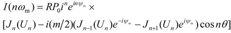 |
(12) |
where Un = 2M sin nθ and R is the photodiode responsivity on the laser emission wavelength. In particular, when n = 1 we have the complex amplitude of the photocurrent I(ωm) at the modulation frequency. Comparing I(ωm) with the complex amplitude of photocurrent detected at the laser output, we come to the following transfer function (when M<<1)
| |
(13) |
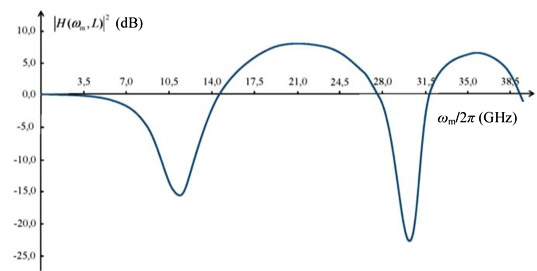
Fig. 1 shows a typical plot of the squared modulus of the transfer function (13), |H(ωm,L)|2, expressed in dB against the modulation frequency fm = ωm/2π for the optical fiber of length L = 10 km with the fiber dispersion coefficient D = 17 ps/(nm km), the laser emission wavelength λ = 1550 nm and the chirp parameters: α = 2, fc = ωc/2π = 2 GHz.
The frequencies of the extrema in Fig. 1 are equal
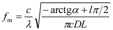 |
(14) |
where odd integers l give the minima, whereas even integers l give the maxima, c is speed of light, is the laser wavelength.
At the minima, the squared modulus of transfer function is
| |
(15) |
whereas at the maxima we have
| |
(16) |
D. Harmonic distortions of transmitted signals
The drive current of the semiconductor laser and the laser output optical power (1) are the single-tone signals with frequency ωm . As it can be seen from expression (11) with complex amplitudes (12), the spectrum of photocurrent detected at the fiber output contains, in addition to the term with frequency ωm , also the higher order harmonics. In other words, the optical signal transmitted through a fiber undergoes the harmonic dispersive distortions. Such distortions are not associated with optical power of the transmitted signals and occur even at low laser light intensities.
It is interesting to note, that all the complex amplitudes (12), except the zero with n=0 and the first one with n=1, vanish when sinθ = 0 . Hence, the signals with frequencies
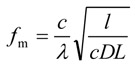 |
(17) |
where l=1, 2, 3... are not subjected to the harmonic distortions. The modulus of transfer function for these signals is equal to unity, that is the power of signals at the input and at the output of the fiber are equal to each other (without attenuation in the fiber). For the fiber-optic link with parameters used in Fig. 1, we obtain for the frequencies (17) the following estimates: fm1 = 27.93 GHz and fm2 = 39.49 GHz.
III. EXPERIMENT
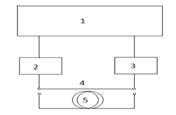
Experimental setup for measuring the intensity modulation response is shown in Fig. 2. The work procedure is as follows. The single-frequency 1550 nm DFB InGaAsP laser (2) is connected to the input of photodetector (3) by a short length of standard single-mode optical fiber (4) about 1 m long and then we determine visually on screen of the analyzer (1) the frequency range where the modulation response has no significant noise and sharp breaks. In this frequency range (in our case 10MHz - 35GHz) the signal power is normalized to unity. Then, the short cable (4) is replaced by a coil of long optical fiber (5) and the output signal is displayed on the screen of analyzer (1). Acting in a similar manner, we can get the intensity modulation response for several delay lines of different fiber lengths. However, the laser light intensity should not be greater than 5-7 dBm because of the risk of stimulated Brillouin scattering and nonlinear distortions.
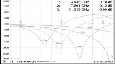
Fig. 3 shows the experimental curves for the output-toinput power ratio of the electrical signals (expressed in dB) versus the modulation frequency fm for several coils of fiber of different length L with the dispersion coefficient D = 17 ps/(nm km). One can readily see a qualitative consistency between the experimental curves and the theoretical curve in Fig 1. Quantitative agreement between the experimental data and the theoretical calculations presented above can be examined with the help of expressions (14-16). Unfortunately, laser vendors do not specify the chirp parameters. Applying the data presented in [3] for α =2.8±0.2 and k = (11.4 ± 0.5) c-1 mW-1 (this gives for the characteristic frequency fc = kP0/2π = (1.8 ± 0.1) GHz at the laser light power P0 = 1mW) we obtain a good agreement between our experimental and theoretical results.
REFERENCES
[1] K. Petermann, Laser Diode Modulation and Noise, Dordrecht: Kluwer Academic Publishers, 1988, pp. 119-144.
[2] E. Peral and A. Yariv, “Large-signal theory of the effect of dispersive propagation on the intensity modulation response of semiconductor lasers,” Journal of Lightwave Technology, vol. 18, pp. 84-89, 2000.
[3] A. Villafranca, J. Lasobras and I. Garcés, “Precise characterization of the frequency chirp in directly modulated DFB lasers,” Proceedings of 6th Spanish Conference on Electronic Devices, pp. 173-176, 2007.
|
Fig. 1. Plot of the squared modulus of transfer function (13) (expressed in dB) against the modulation frequency fm.= ωm/2π |
|
Fig. 2. Experimental setup for measuring the intensity modulation response. |
|
Fig. 3. Output-to-input signal power ratio (expressed in dB) versus the modulation frequency for several lengths of a single-mode fiber. |
Мы будем рады ответить на них!